Link Chain Sprocket Design

Sprockets Cobalt Chains
Round Link Sprockets John King Chains
Chains Sprockets
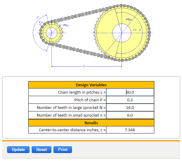
Sprocket Center Distance Equation And Calculator Engineers Edge Www Engineersedge Com
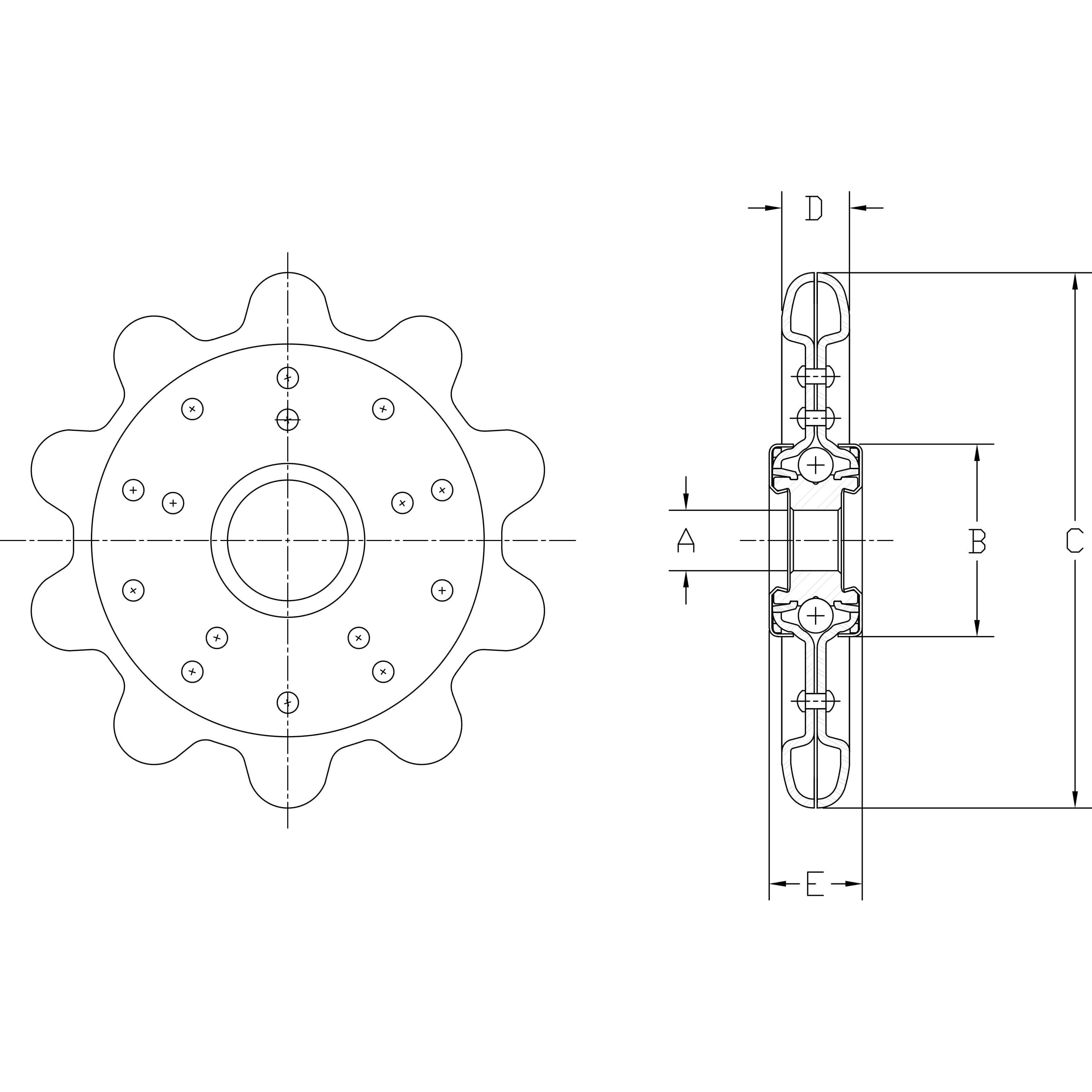
Detachable Link Sprocket Idler Aetna Bearing Company

Calculating Roller Chain Length Inventor 2016 Autodesk Knowledge Network

22 15 with welded teeth or in some cases cast with a solid pocket tooth form.
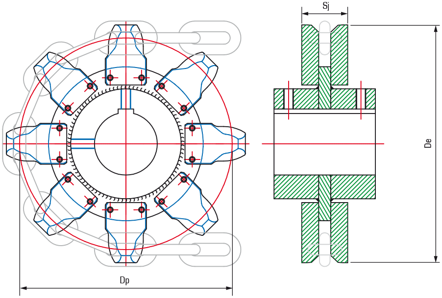
Link chain sprocket design. Teeth dp de sj inches 1450 6t 6 7 637 9 137. A g2 attachment outer plate. B g2 attachment welded or rivetted to link plate. Sprocket tooth design formulas refer to fig.
8 3 roller and bush chains. G attachments are normally fitted only to one side of the chain. The shape of the tooth form. 2 design of steel roller chains.
Sprockets consist of a disk with straight teeth projecting radially. 1 sprocket tooth geometry the tooth form of a sprocket is derived from the geometric path described by the chain roller as it moves through the pitch line and pitch circle for a given sprocket and chain pitch. Sprockets will only work correctly with chain and other sprockets if they are on parallel shafts and the teeth are in the same plane. Table 22 26 jk code no.
The snap together feature also makes the chain adjustable to any loop length without the need for special splicing tools. The high standard of quality assurance conforms with the high requirements of the automotive industry of iso 9002 1987 and other national and interna. Plate then the shroud of the chain sprocket has to be removed to clear the plate. Serv o link chain and sprockets provide the designer with a unique and highly versatile means of transmitting rotary power.
Serv o link s unit link chain design eliminates the need for a master link.
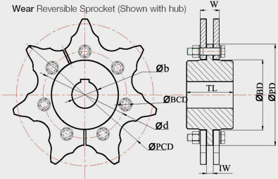
Conveyor Sprocket Standard Conveyor Sprockets Wear Reversible Sprocket Dual Sprockets Anand Gujarat India

Roller Chain An Overview Sciencedirect Topics
Https Www Blocklayer Com Chain Sprocket Aspx

Chain And Sprocket Designing Assembling Motion Study In Solidworks Youtube

Pdf Analysis Of Roller Chain Drive System With Multi Flexible Body Dynamics Methodology
Sprocket Diameter Calculator

Practical Machinist Largest Manufacturing Technology Forum On The Web

Standard Roller Chain Drive Design

Design Of Machine Elements Chain Drives Introduction And Problem Youtube

Chains And Sprockets Ansi 25 Chain
Https Www Matec Conferences Org Articles Matecconf Pdf 2018 43 Matecconf Oradea2018 02003 Pdf

Sprockets Wheel Link Chain Sprocket Trailing Wheel Manufacturer From Kolkata

Chain Sprocket It Can Be Used In Bikes This System Consists Of An Endless Chain Closed Whose Links Engage With Sprockets Gears Which Are Attached To The Ax

